


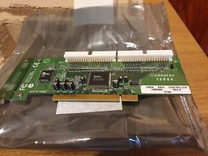


PATA IDE EIDE Internal Interface Card for PCI
One concern with the march of technology is that sometimes you still need access to older hardware even after the majority of the world has moved on. This is the case with the IDE drive interface, which you can also call PATA for parallel ATA, as opposed to SATA or serial ATA. While it was a powerful and flexible interface for the time, the problem it faces now is that computers no longer have IDE ports to support compatible interfaces. Luckily, you can buy controller cards, which put one or more IDE connectors on a single PCI card. One card with two connectors can support up to four hard drives.
How Does IDE Work?
IDE works according to the ATA specification. The original ATA interface used a forty-pin connector with a corresponding 40-pin cable that later gave way to a so-called 80-pin cable for the faster ATA-100 and ATA-133 specifications. Note that the later specification still had 40 pins, but it was now an 80-conductor cable with shielding for better high-speed data transfer. The high number of wires was due to sending 32-bits of data along one cable in parallel. You can differentiate the two cables as follows:
40-Pin Cable: Notable for a red stripe running to pin one to show which end of the cable went where. It could support two drives and often used jumpers to determine which hard drive was the master, or primary, on the system and which was the slave.
80-Pin Cable: Recognizable for the greater number of thinner conductors, this cable featured three connectors that were color coded. Gray went to the motherboard slot, black to the master, and blue to the slave.
What is PCI?
PCI stands for Peripheral Component Interconnect and was the standard PC expansion bus before the introduction of PCI-Express. Unlike PCI-Express, which is a serial interface with each connector having between four and sixteen dedicated lanes, PCI used a shared bus architecture where each slot connected to a common bus. This simplified the controller but could lead to device conflicts and limited bandwidth to individual hard drives. While Windows usually managed things with plug and play, sometimes you had to manually configure devices so they would work together. One trick was to install your PCI cards in a specific order so certain ones could grab the resources they needed first. PCI had several different iterations with variations of the same protocol including Mini PCI for laptops.
- PCI: First implemented with a 32-Bit 33 MHz specification using 5-Volt signaling, this original standard later dropped to 3.3 Volts with keyed slots making sure that you did not use the wrong PCI card. This later extended to 66 MHz and 64-bits but neither was common.
- PCI-X: Standing for PCI-eXtended, not PCI Express, this was the server-oriented version. Based on PCI, it almost universally used 64-bit slots and much higher speeds, with 66 MHz to 133 MHz being common. While still a shared bus, it offered several times the bandwidth of traditional PCI.
Choosing the Right Controller Card
While installing an old and relatively slow drive may seem odd in a world of solid state drives with high data transfer rates, sometimes you need the old systems. With the right controller card, you can give yourself two or more internal ports with the associated disk controllers to run any desktop hard drive even on a modern system. ATA desktop drives relied on a shared bus, so the more devices on a given controller the less bandwidth each one had access to. This was in stark contrast to SATA, which gives each hard drive its own dedicated channel. When installing a PCI card always check the space inside your case, you may need a low-profile card in smaller spaces that cannot accept a full-height PCI card.